Applications:
|
||||||||||||||||
Features:
|
||||||||||||||||
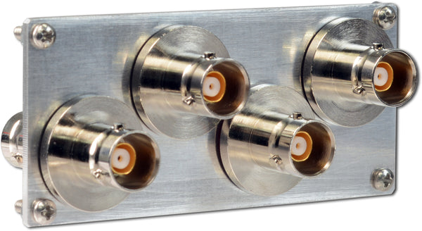
Description:The PRL-854DC-RM is a 1 x 4, DC router designed for both ground and signal connect/disconnect applications. A signal connected to input D can be routed to output Q1, Q2, Q3 or Q4. It can also be used as a 4:1 scanner in the reverse direction, in that signals connected to the Q inputs can be scanned one at a time at the D output. The PRL-854DC-RM has BNC I/O connectors isolated from the case. Each unit is provided with a 4-position rotary switch for manual channel selection and four LEDs for channel identification. Each unit also has 4 x 2 stick pins (pulled up to +5 V via 4.99 kΩ resistors) for remote TTL/CMOS logic control inputs. The pin designations and truth tables for the logic inputs are shown in the following table. When the rotary switch is set to the fully clockwise position the logic inputs are left open, A0 and A1 are high, and channel Q4 is selected. Jumpers or remote inputs may be used to pull the pins low. A second set of control pins is commoned to the first set, permitting a daisy-chained control cable to program multiple units simultaneously. Because the control pins are pulled up to +5 V, the controller does not need to supply any current to control the unit. It needs only to sink 1 mA per pin.
Table I: Logic Input Truth table The PRL-854 series can be controlled from the PRL-USBIO-1 module (LabVIEW primitives available), the PRL-ETHIO-1 module, or any external controller that can pull the control pins down. The PRL-854DC-RM is housed in a 1.3-in. x 2.9-in. x 2.9-in. aluminum extrusion and is provided with a ±8.5 V AC/DC adaptor. If mounting is desired, a pair of 35001420 mounting brackets can accommodate two PRL modules of the same length. A number of PRL modules can also share a single ±8.5 V AC/DC adaptor using the PRL-730 voltage distribution module. Please see the Accessories Section for more detail. |
||||||||||||||||

The PRL-854 series is well suited to cascading, in either direction, for creating configurations with larger channel counts and/or special applications, with no engineering required. Please see this Application Note where our sister company designed a set of PRL-854 and PRL-854DC units into a low-noise, high-speed, flexible test multiplexer:
SPECIFICATIONS (0° C ≤ TA ≤ 35° C)*
| Symbol | Parameter | Min | Typ | Max | Unit | Comment |
|---|---|---|---|---|---|---|
| RIN(RM) | Input Resistance, Logic Inputs | 4.99 | kΩ | Pulled up to +5 V | ||
| VIH | Logic Input Hi Level | 2 | 2 | 5 | V | |
| VIL | Logic Input Lo Level | -0.50 | 0 | 0.50 | V | |
| PMAX1 | Max switching power AC (R load) | 62.5 | VA | |||
| PMAX2 | Max switching power DC (R load) | 30 | W | |||
| RMAX | Max contact resistance | 100 | mΩ | |||
| VMAX | Max input AC voltage | 125 | V | |||
| VMIN | Input DC voltage | 10 mV | 110 V | |||
| I | Switching current | 10 uA | 1 A | |||
| Switch Time | 3 | ms | ||||
| Expected Life cycles | > 106 | |||||
| VDC | DC Input Voltage | 7.5 | 8.5 | 12 | V | |
| IDC | DC Input Current | 90 | 110 | mA | ||
| VAC | AC/DC Adapter Input Voltage | 100 | 115 | 127 | V | |
| Logic Input for Remote Operation | 4 x 2 pins (A0, A1, G1, G2) | See Table 1 | ||||
| Size | 1.3 x 2.9 x 2.9 | in | ||||
| Weight, excluding AC adapter | 7 | Oz | ||||
| Shipping weight, including AC adapter | 4 | lb. | ||||


