Applications:
|
|
Features:
|
|
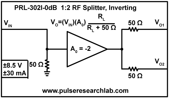
DescriptionThe PRL-302I-0dB is a DC coupled, inverting, 0 dB 1:2 RF splitter amplifier. It has two identical 50 Ω back-terminated outputs and a 50 Ω-to-ground terminated input. The 0 db gain, VO = VIN (RL = 50 Ω), allows multiple amplifiers to be cascaded for signal distribution applications. One pair of these amplifiers (one inverting, one non-inverting) can produce two pairs of complementary RF signals when driven by a single input using a 6 dB passive power divider. This splitter amplifier has been optimized both for pulse response and for CW response, so that output overshoots and ringing for a fast pulse input are much smaller than those from amplifiers designed mainly for CW applications. With a 50 Ω back termination at each output, this amplifier can drive long transmission lines with or without load terminations. For optimum output response both outputs should be terminated into 50 Ω. Each amplifier is housed in a 1.0 x 1.3 x 2.2-in. aluminum enclosure and is supplied with a ±8.5 V AC/DC adapter. Aside from the I/O and power connections, no other set up or connection is required. These amplifiers are part of the PRL family of Mini Modular Instruments (MMIs). |

Fig. 1B: PRL-302I-0dB Top Cover Decal
SPECIFICATIONS (0° C ≤ TA ≤ 35° C)*
| SYMBOL | PARAMETER | PRL-302I-0dB | UNIT | Comments | ||
|---|---|---|---|---|---|---|
| Min | Typ | Max | ||||
| Rin | Input Resistance | 49.5 | 50.0 | 50.5 | Ω | |
| Rout | Output Resistance | 49.5 | 50.0 | 50.5 | Ω | |
| AO | Open Circuit Voltage Gain | -2 | x | RL=1 MΩ | ||
| AL | Loaded Voltage Gain | -1 | x | RL=50 Ω | ||
| AdB | Voltage Gain in dB | 0 | dB | RL=50 Ω | ||
| IDC | DC Input Current (NL) DC Input Current (VO = ±1.25V) |
±20 ±30 |
±25 ±35 |
mA | ||
| VDC | DC Input Voltage | ±7.5 | ±8.5 | ±12 | V | |
| VAC | AC/DC Adapter Input Voltage | 103 | 115 | 127 | V | |
| tPLH | Propagation Delay to output ↑ | 1.2 | ns | |||
| tPHL | Propagation Delay to output ↓ | 1.2 | ns | |||
| tR/tF | Small Signal Rise/Fall Times | 650 | 800 | ps | 10%-90%, VO = ±0.2 V | |
| BW1 | Small Signal 3 dB BW | 437 | 530 | MHz | ||
| tR/tF | Large Signal Rise/Fall Times | 1.50 | 1.75 | ns | 10%-90%, VO = ±1.25 V | |
| BW2 | Large Signal 3 dB BW | 200 | 233 | MHz | ||
| tSKEW | Skew between outputs | 200 | 500 | ps | ||
| Size | 1.0 x 1.3 x 2.2 | in | ||||
| Weight | 4 | Oz | w/o AC adapter | |||
| Shipping weight | 4 | lb | with AC adapter | |||


