Applications:
|
|
Features:
|
|
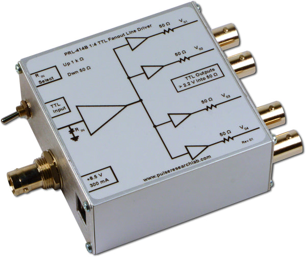
DescriptionThe PRL-414C is a 1:4 fanout 50 Ω TTL Line Driver. It is intended for distribution of high-speed clock and logic signals to multiple loads via long lines. The 50 Ω back-terminated outputs can drive long lines with or without 50 Ω load terminations; With 50 Ω load terminations, however, all outputs of the PRL-414C can drive 100 ft of 50 Ω cables at clock rates greater than 80 MHz. The inner two outputs of the PRL-414C can be inverted via a toggle switch to create two differential output channels that are compatible with many differential receivers, including most RS-422 receivers and our own PRL-425 series. In 1:4 output mode the performance of the PRL-414C is generally similar to that of the PRL-414B, upon which it is based. The input resistance of the PRL-414C can be selected to be either 50 Ω or 1 kΩ by a switch. The 1 kΩ-input is desirable when interfacing with low power circuits. All I/O’s are DC coupled and have BNC or SMA connectors. The PRL-414C is housed in a 1.3 x 2.9 x 2.9-in. extruded aluminum enclosure and is supplied with a ±8.5 V/± 1.8 A AC/DC Adapter. A maximum of four units can share a single AC/DC adapter using the PRL-730 voltage distribution module. If mounting is needed, a pair of the #35001420 mounting brackets can accommodate any two PRL modules of the same length. A block diagram showing the equivalent input and output circuits of the PRL-414C is shown in Fig. 1.
|
 Fig. 1, PRL-414C Block Diagram