Applications:
|
|
Features:
|
|
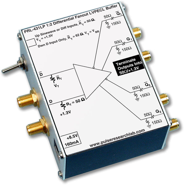
DescriptionThe PRL-427LP is a 2-channel LVPECL to differential NCML Logic Level Translator module. Each channel has a single-ended or differential LVPECL input and a ground-referenced differential 35 Ω NCML output. The NCML DC output logic Hi/Lo levels are 0 V and -350 mV, respectively, when terminated to ground-referenced 50 Ω loads. A switch selects either single-ended or differential inputs, as shown in Fig. 1. In the differential input mode, both inputs D and D are terminated internally into 50 Ω/VTT, where VTT is equal to +1.3 V for LVPECL. In the differential input mode, therefore, either one or both inputs can accept AC coupled signals as well. In the single input mode, signals should be connected to the D inputs only. The D inputs are switched internally to VBB, nominally +2.0 V for LVPECL, and termination resistors RT for the D input channels are changed to 62 Ω. These Logic Level Translators are designed specifically for use in testing and interfacing of high speed digital communications circuits, where conversion between LVPECL and NCML logic signals is often required. The PRL-427LP is part of the Mini Modular Instrument™ (MMI) family that find increasing applications in high speed digital data recording instruments, transient recording instruments and other high speed measurement equipment where LVPECL and NCML signals are often specified. |

(0° C ≤ TA ≤ 35° C)*
Unless otherwise specified, all logic level and dynamic measurements are made with all outputs terminated into 50 Ω/VTT, where VTT = 0 V for NCML outputs.
| SYMBOL | PARAMETER | PRL-427LP | UNIT | ||
|---|---|---|---|---|---|
| Min | Typ | Max | |||
| RIN | Input Resistance | 49.5 | 50.0 | 50.5 | Ω |
| ROUT | Output Resistance | 35 | Ω | ||
| VTT | D Input Termination Voltage (fixed) | 1.18 | 1.30 | 1.43 | V |
| VT1 | D Input Termination Voltage | 1.18 | 1.30 | 1.43 | V |
| VT2 | D Input Termination Voltage (variable) | 1.80 | 2.00 | 2.20 | V |
| VIL | Input Lo Voltage | 1.35 | 1.48 | 1.67 | V |
| VIH | Input Hi Voltage | 2.08 | 2.28 | 2.42 | V |
| VOL | DC Output Low Level | -0.35 | V | ||
| VOH | DC Output High Level | 0 | V | ||
| VOPP1 | Output Logic Swing from DC-500MHz | 300 | 350 | mV | |
| VOPP2 | Output Logic Swing from 500MHz-1GHz | 275 | 300 | mV | |
| VOPP3 | Output Logic Swing from 1GHz -1.5GHz | 225 | 260 | mV | |
| VOCM | Output Common Mode Voltage | -200 | mV | ||
| IDC1 | DC Input Current, +8.5 V | 160 | mA | ||
| IDC2 | DC Input Current, -8.5 V | -315 | mA | ||
| VDC | DC Input Voltage | ±7.5 | ±8.5 | ±12.0 | V |
| VAC | AC/DC Adapter Input Voltage | 108 | 120 | 132 | V |
| tPLH | Propagation Delay to output ↑ | 1.5 | ns | ||
| tPHL | Propagation Delay to output ↓ | 1.5 | ns | ||
| tR/tF | Rise/Fall Times (10-90%) | 650 | 750 | ps | |
| TSKEW | Skew between any 2 outputs | 40 | 75 | ps | |
| VINI | Minimum Input Voltage @ 150 MHz | 20 | 10 | mVpp | |
| VINII | Minimum Input Voltage @ 250 MHz | 20 | 10 | mVpp | |
| fMAX | Max Clock Frequency | 1250 | 1500 | MHz | |
| Size | 1.3H x 2.9W x 3.9D | in. | |||
| Weight, excluding AC adapter | 7 | Oz | |||
| Shipping weight, including AC adapter | 4 | lb. | |||


