Applications:
|
||||||||||||||||||||||||||||||||||||||||||||||||||||||||||||||||||||||||||||||||||||||||||||||||||||||||||||||||||||||||||||||||||||||||||||||||
Features:
|
||||||||||||||||||||||||||||||||||||||||||||||||||||||||||||||||||||||||||||||||||||||||||||||||||||||||||||||||||||||||||||||||||||||||||||||||
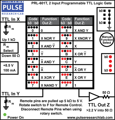
DescriptionThe PRL-601T is a 2-input, TTL logic gate with 16 selectable functions, capable of operating at input clock frequencies in excess of 100 MHz. The input resistance of the two TTL inputs can be selected to be 1 kΩ or 50 Ω by a common toggle switch. The back-matched 50 Ω output of this module can drive long lines and deliver greater than 2.2 V into 50 Ω loads. The TTL Output Z will be a logical function of the two TTL inputs X and Y, as shown in the truth table, below. The logic function can be selected manually or by a remote controller, such as the PRL-USBIO-1. Each unit is housed in a 1.3 x 2.9 x 2.9-in. extruded aluminum enclosure with BNC or SMA I/O connectors. A ±8.5V AC/DC Adapter, 120/220 VAC manually switchable, is supplied with each unit. A block diagram of the PRL-601T is shown in Fig. 1. Manual Programming: Rotate the selector to manually select one of the 16 available logic functions. The corresponding binary code will be displayed on the 4 LEDs, b3-b0. Two selector styles are available—a recessed version that must be rotated with a screwdriver, and a version with a knob that can be rotated with fingers. Remote Programming: To program the unit remotely, e.g. from a PRL-USBIO-1, rotate the selector knob to “F”, and then apply TTL-compatible levels to control bits b3-b0. The corresponding binary code will be displayed on the 4 LEDs. The control pins are pulled up to 5 V via 5 K resistors; therefore the remote controller does not need to supply any current. Ordering information: To the base model number, PRL-601T, append a selector style:
For example PRL-601T-K-BNC has a finger knob and BNC I/Os. A version with SMA I/Os may be offered at a later date.
|
||||||||||||||||||||||||||||||||||||||||||||||||||||||||||||||||||||||||||||||||||||||||||||||||||||||||||||||||||||||||||||||||||||||||||||||||

Sample output waveform is shown below, generated by an Excel-based simulator:


The PRL-601T can be used for many applications, including the following:
- Pulse Picking
- Clock doubling
The connector spacing of the PRL-601T is designed to facilitate cable-less cascading by connecting the output of one or two units to the inputs of another unit with BNC-M/BNC-M couplers.
In the following examples three PRL-601T units are cascaded to form a 4-input logic gate:


(0° C ≤ TA ≤ 35° C)*
| SYMBOL | PARAMETER | Min | Typ | Max | UNIT | Comments |
|---|---|---|---|---|---|---|
| RINLo | Input Resistance, 50 Ω | 49.5 | 50.0 | 50.5 | Ω | |
| RINHi | Input Resistance, 1 kΩ | 990 | 1000 | 1010 | Ω | |
| IDC1 | DC Input Current | 100 | 125 | mA | ||
| VDC | DC Input Voltage | 7.5 | 8.5 | 12.0 | V | |
| VAC1 | AC/DC Adapter Input Voltage, 120 VAC | 103 | 115 | 127 | V | |
| VAC2 | AC/DC Adapter Input Voltage, 220 VAC | 206 | 230 | 254 | V | |
| VIH | Input Hi Level | 2.0 | 5.0 | V | ||
| VIL | Input Lo Level | -0.5 | 0.8 | V | ||
| VOH1 | Output Hi Level, RLOAD = 50 Ω | 2.2 | 2.5 | V | ||
| VOH2 | Output Hi Level, RLOAD = 1 MΩ | 4.6 | 5.0 | V | ||
| VOL1 | Output Lo Level, RLOAD = 50 Ω | 0.15 | 0.25 | V | ||
| VOL2 | Output Lo Level, RLOAD = 1M Ω | 0.3 | 0.5 | V | ||
| TPLH | Propagation Delay to f/n output ↑ | 4.0 | 5.0 | ns | ||
| TPHL | Propagation Delay to f/n output ↓ | 6.0 | 7.5 | ns | ||
| tr | Rise Time (10%-90%) | 900 | 1000 | ps | ||
| tf | Fall Time (10%-90%) | 900 | 1000 | ps | ||
| FMAX | Max clock frequency | 100 | MHz | RIN = 50 Ω | ||
| Size | 1.3 x 2.9 x 2.9 | in. | ||||
| Weight | 1 | lb. | ||||
| Shipping weight, incl. AC adapter | 4 | lb. | ||||


