Applications:
|
|
Features:
|
|
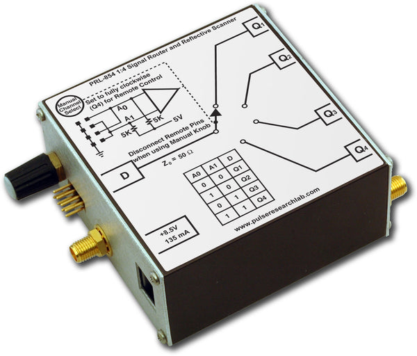
DescriptionThe PRL-852A-RM is a dual channel, DC coupled 'A/B' switch designed for switching microwave and sub-nanosecond rise time signals in the 50 Ω environment. It is a reflective switch in that the unselected port, A or B, is not terminated into 50 Ω. Therefore, a signal connected to the unselected port will be reflected. The reflective switch is intended mainly for routing a signal from port C to either port A or B, where not terminating the unselected port into 50 Ω is desirable. It can also be used as a scanner when not terminating the unselected port is acceptable. When a switch is in the Up position, the upper pin is pulled up to 5 V via a 4.99KΩ resistor, and the Port A is selected. A logic Hi of +3.5 V minimum applied to the upper pin is sufficient to maintain the selection of Port A. The lower pin is GND. Shorting the upper pin to GND or pulling it below 0.5 V selects Port B. The two channels 1 and 2 are independent, and may be switched separately. The toggle switch for a given channel should be in the Up position for remote control. Remote pins should be disconnected in manual mode, otherwise the switch in the Down position will short the external control circuit to GND. The unit is housed in an extruded aluminum enclosure and supplied with a ±8.5V AC/DC adapter. It can also be powered by a +7.5 V to +12 V DC power supply. Unless otherwise specified, dynamic measurements are made with all outputs terminated into 50 Ω. The PRL-852A-RM replaces both the PRL-852 and PRL-852-RM in all applications, as it provides both manual and remote control in a single design. Please note that the new control pin polarity is reversed with respect to the old design, with the benefit that that remote circuit no longer needs to provide any current to the device.
|

PRL-852A Block Diagram
SPECIFICATIONS (0° C ≤ TA ≤ 35° C)*
| Symbol | Parameter | Min | Typ | Max | Unit | Comment |
|---|---|---|---|---|---|---|
| tr/tf1 | Rise/Fall Times (10%-90%) | 130 | 155 | ps | SMA | |
| tr/tf2 | Rise/Fall Times (10%-90%) | 150 | 200 | ps | BNC | |
| BW1 | Equivalent 3 dB Bandwidth | 2.25 | 2.69 | GHz | SMA | |
| BW2 | Equivalent 3 dB Bandwidth | 1.75 | 2.30 | GHz | BNC | |
| RIN(RM) | Input Resistance, Logic Inputs | 4.99 | KΩ | Pulled up to +5 V | ||
| VIH | Logic Input Hi Level | 2 | 2 | 5 | V | |
| VIL | Logic Input Lo Level | -0.50 | 0 | 0.50 | V | |
| VSWR1 | 25 MHz ≤ f ≤ 1.25 GHz | 1.15:1 | 1.25:1 | SMA | ||
| VSWR2 | 25 MHz ≤ f ≤ 1.25 GHz | 1.60:1 | 1.80:1 | BNC | ||
| VSWR3 | 1.25 GHz ≤ f ≤ 2.4 GHz | 2.70:1 | 3.50:1 | SMA | ||
| VSWR4 | 1.25 GHz ≤ f ≤ 2.4 GHz | 4.20:1 | 4.80:1 | BNC | ||
| VO/VIN1 | Insertion Loss, Selected Channel, 625 MHz ≤ f ≤ 1.25 GHz | 2.0 | 2.6 | dB | ||
| VO/VIN2 | Insertion Loss, Selected Channel, 1.25 GHz ≤ f ≤ 2.4 GHz | 3.4 | 4.2 | dB | ||
| VO/VIN3 | Insertion Loss, Selected Channel, 2.4 GHz ≤ f ≤ 3.0 GHz | 5.0 | dB | |||
| VO/VIN4 | Isolation, Non-selected Channels, 625 MHz ≤ f ≤ 1.25 GHz | 34 | 42 | dB | ||
| VO/VIN5 | Isolation, Non-selected Channels, 1.25 GHz ≤ f ≤ 2.4 GHz | 32 | 40 | dB | ||
| VO/VIN6 | Isolation, Non-selected Channels, 2.4 GHz ≤ f ≤ 3.0 GHz | 33 | dB | |||
| TPLH | Propagation Delay to Output | 600 | 1000 | ps | ||
| TSKEW | Skew between any 2 outputs | 10 | 25 | ps | ||
| VIN Max | Maximum Input Voltage | 30 | V | |||
| IMAX | Maximum Switching Current | 0.5 | A | |||
| Switch Time | 6 | ms | ||||
| Expected Life cycles | > 106 | |||||
| VDC | DC Input Voltage | 7.5 | 8.5 | 12 | V | |
| IDC | DC Input Current | 85 | 110 | mA | ||
| VAC | AC/DC Adapter Input Voltage | 100 | 115 | 127 | V | |
| Logic Input for Remote Operation | 2 x 2 pins (A0, A1, G1, G2) | |||||
| Size | 1.3 x 2.9 x 1.5 | in | ||||
| Weight, excluding AC adapter | 7 | Oz | ||||
| Shipping weight, including AC adapter | 4 | lb. | ||||


