Applications:
|
||||||||||||||||
Features:
|
||||||||||||||||
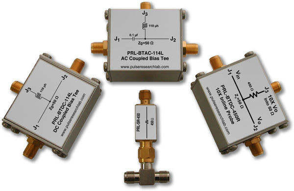
DescriptionThe PRL Series of Coupling and Termination Modules are two-terminal devices containing components which are series-connected, shunt-connected, or combination of both. They are intended for use in general purpose lab and production test environments. For example, in a given test setup one may need to insert a DC Block, a 50 Ω Termination, a Feed-through Decoupling Capacitor, an RF Choke, a Series Diode, etc. in order to accommodate a change in the test requirement. As of this date, the following modules are available, and more are being developed:
As of February 2011, PRL has discontinued the ready-to-use attenuator series, due to low demand. We will honor and support all outstanding quotations and orders, but we will not be offering new items for sale in quantities of less than 100. For volume orders, please contact sales@pulseresearchlab.com . To build your own attenuator, please see our Signal Conditioning Kits and our Custom Attenuators application note. |
||||||||||||||||

A DC block connected between a source and a load is shown in Fig.1, where RT is the total resistance of the circuit, consisting mainly of the sum of the source and load resistance, and C is the coupling capacitor. The time constant τ of the circuit is RTC, and it has the unit of ms if RT is in Ohms and C is in µf, or ns if RT is in kΩ and C is in pf. In most practical cases, the stray capacitance across the load can be neglected. The case where RS=RL=50 Ω is of special interest, where RT is 100 Ω, and this value is used in Table I below.
When a voltage step with amplitude E is applied to the input at t0, the output immediately rises to E/2. At t0+,the output starts to decay towards zero with a time constant τ. After 4τ, the output will have discharged 98% of E/2 and is nearly at ground potential.
For coupling pulse signals, it is clear that one needs a capacitor large enough so that the output signal remains essentially rectangular in shape as the pulse duration increases. Table I lists the coupling capacitor values verses % pulse level tilt* for different values of pulse width. Instead of the exponential decay, a linear decay approximation of the output is used.
It should be noted that the value of RS is generally not 50 Ω when the drive circuit is an ECL device, because the output resistance of an emitter follower is typically 5 Ω. Therefore, the values shown in Table I need to be modified when AC coupling a signal from an ECL emitter follower. A simple and quick approximation is to either divide all the PW values by two or multiply the % tilt values by two.
| C(µf) | f3 dB | τ=RTC | PW (1% tilt) | PW (2% tilt) | PW (5% tilt) | PW (10% tilt) |
|---|---|---|---|---|---|---|
| 0.01 | 159 KHz | 1 µs | 10 ns | 20 ns | 50 ns | 100 ns |
| 0.1 | 15.9 KHz | 10 µs | 100 ns | 200 ns | 500 ns | 1 µs |
| 1.0 | 1.59 KHz | 100 µs | 1 µs | 2 µs | 5 µs | 10 µs |
| 10 | 159 Hz | 1 µs | 10 µs | 20 µs | 50 µs | 100 µs |
| 100 | 15.9 Hz | 10 µs | 100 µs | 200 µs | 500 µs | 1 ms |
Table I. Transmission of a rectangular pulse train through a high-pass filter with time constant t=RTC, f3 dB=1/2πRTC. RT=100 Ω.
* For a thorough treatment of this subject, please see Millman and Taub, Pulse, Digital, and Switching Waveforms.
(0° C ≤ TA ≤ 35° C)*
DC Blocks, Series-Connected Capacitor:
| Model No. | Capacitance value/Type | VSWR | Tr/3dB BW | Application |
|---|---|---|---|---|
| PRL-SC-104A | 0.1 µf, ±10%, 30 V,X7R | <1.1@3.0 GHz | 40 ps/>8 GHz | AC Coupling |
| PRL-SC-225A | 2.2 µf, ±20%, 30 V, Z5U | <1.2@2.5 GHz | 50 ps/7 GHz | AC Coupling |
RF Chokes, Series-Connected Inductor:
| Model No. | Inductance Value | Irms Max | DCR max | SRF Typical | Application |
|---|---|---|---|---|---|
| PRL-SL-102A | 1000 nh, ±5% | 300 mA | 3.5 Ω | 400 MHz | RF Isolation |
| PRL-SL-103A | 10 µh, ±5% | 300 mA | 3 Ω | 60 MHz | RF Isolation |
Series-Connected Schottky or PN Junction Diode:
| Model No. | Equivalent Device Type | VBR | If @ 1V Vf | CT | Application | Comments |
|---|---|---|---|---|---|---|
| PRL-SSDP | HSMS-2813/-2814 (Schottky) | 20 V | 70 mA | 2.4 pf | RF Detector | 2 devices in // |
| PRL-SDP | 1N914 | 100 V | 10 mA | 4 pf | General purpose detector |
Series-Connected Resistors:
| Model No. | Resistance Value | Max. Vr | Application |
|---|---|---|---|
| PRL-SR-50 | 50 Ω ±1% | 5 V | Back 50 Ω Term. |
| PRL-SR-450 | 450 Ω ±1% | 10 V . | 10X attenuator |
| PRL-SR-950 | 950 Ω ±1% | 15 V. | 20X attenuator |
| PRL-SR-106A | 1 MΩ ±1% | 100 V | Current source |
Shunt-Connected Capacitors:
| Model No. | Value/Type | Application |
|---|---|---|
| PRL-FTC-104A | 0.1 uf, ±10%, 30 V,X7R | Decoupling/AC short |
Shunt-Connected Resistive Terminations:
| Model No. | Value/Type | Max Vr/Ir | Application/Description |
|---|---|---|---|
| PRL-ACT-50 | 50 Ω, ±1% | 5 V Max. | Dual AC Coupled 50 Ω termination |
| PRL-DCT-50 | 50 Ω, ±1% | 5 V Max. | Dual DC Coupled 50 Ω termination |
| PRL-FTR-50 | 50 Ω, ±0.5% | 5 V Max. | Precision Feed-Thru Termination. |
| PRL-FTR-0 | 0 Ω, +0.005 Ω | 500 mA Max. | Short circuit termination |
Shunt-Connected Diodes:
| Model No. | Type | VBR | If @ 1V Vf | CT | Application | Comments |
|---|---|---|---|---|---|---|
| PRL-FTSDPD | HSMS-2813/-2814, SBD | 20 V | 70 mA | 2.4 pf | +Signal clipping | Grounded Cathode, 2 devices in // |
| PRL-FTSDND | HSMS-2813/-2814, SBD | 20 V | 70 mA | 2.4 pf | -Signal clipping | Grounded Anode, 2 devices in // |
Attenuators:
As of February 2011, PRL has discontinued the ready-to-use attenuator series, due to low demand. We will honor and support all outstanding quotations and orders, but we will not be offering new items for sale in quantities of less than 100. For volume orders, please contact sales@pulseresearchlab.com . To build your own attenuator, please see our Signal Conditioning Kits and our Custom Attenuators application note.