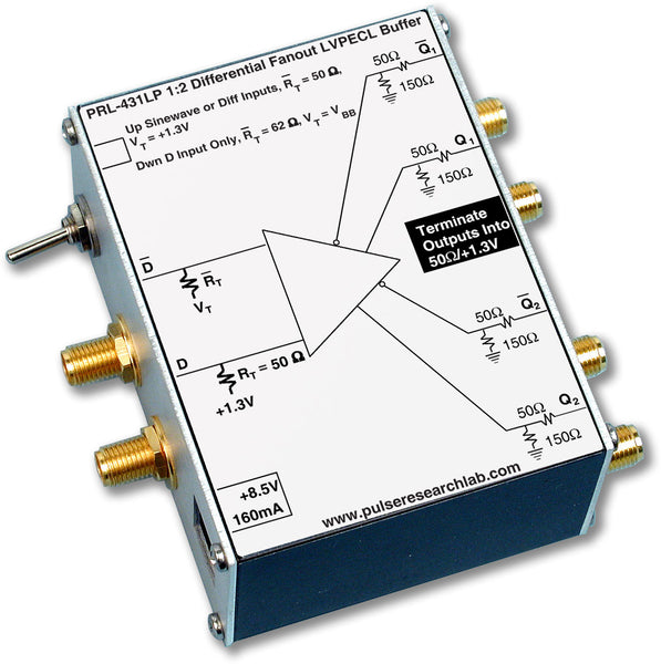
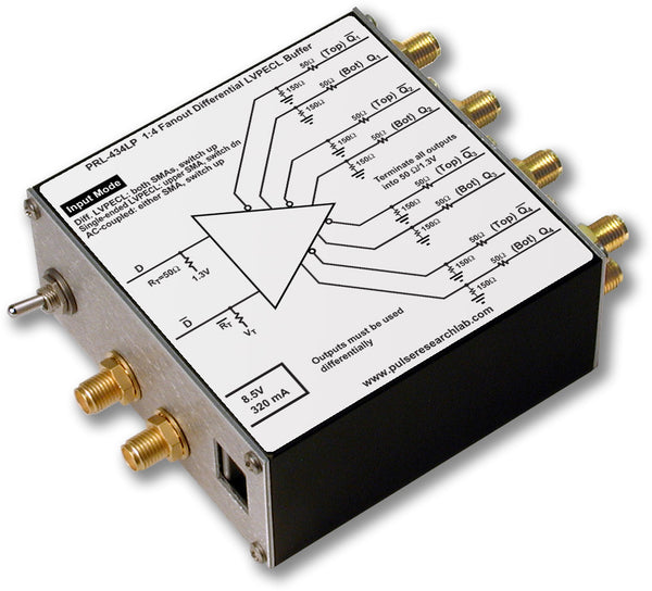
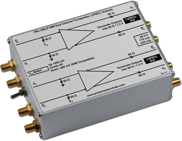
Applications:
|
|
Features:
|
|
DescriptionThe PRL-420LPD translator converts TTL/CMOS logic to LVPECL levels. Each unit has a switch-selectable 1.5 V or 1 V input threshold voltage with a fixed 50 Ω input termination. The complementary LVPECL outputs from the PRL-420LPD are suitable for driving 50 Ω loads terminated to +1.3 V. The outputs can also drive AC-coupled or floating 50 Ω loads. These Logic Level Translators are designed specifically for use in testing and interfacing of high speed digital communications circuits, where conversions from TTL/CMOS level signals to LVPECL level signals are often required. They are ideal building blocks that complement other PRL Logic Level Translators, such as the PRL-450ND, PRL-450PD, PRL-460NPD and PRL-460PND, etc. in systems integration applications where interconnections of mixed logic signals are often necessary. |

(0° C ≤ TA ≤ 35° C)*
| Symbol | Parameter | PRL-420LPD | Unit | ||
|---|---|---|---|---|---|
| Min | Typ | Max | |||
| Rin | Input Resistance | 49.5 | 50 | 50.5 | Ω |
| Rout | Output Resistance | 49.5 | 50 | 50.5 | Ω |
| VTOSH | Input Threshold Voltage (High) | 1.4 | 1.5 | 1.6 | V |
| VTOSL | Input Threshold Voltage (Low) | 0.9 | 1.0 | 1.1 | V |
| VOL | Output Low Level | 1.5 | 1.7 | 1.8 | V |
| VOH | Output High Level | 2.3 | 2.5 | 2.7 | V |
| IDC1 | DC Input Current, +8.5 V | 135 | 200 | mA | |
| IDC2 | DC Input Current, -8.5 V | -325 | -350 | mA | |
| VDC | DC Input Voltage | ±7.5 | ±8.5 | ±12 | V |
| VAC | AC/DC Adapter Input Voltage | 103 | 115 | 127 | V |
| tPLH | Propagation Delay to output | 2 | ns | ||
| tPHL | Propagation Delay to output | 2 | ns | ||
| tr/tf(1) | Rise/Fall Times (20%-80%) | 1100 | 1250 | ps | |
| tSKEW1 | Skew: VO↑↔VO↓ | 200 | 500 | ps | |
| tSKEW2 | Skew: VO1↑↔ VO2↑ | 200 | 500 | ps | |
| fMAX VTOSH |
Max Clock Frequency Input Threshold Voltage (High) |
200 | 300 | MHz | |
| fMAX VTOSL |
Max Clock Frequency Input Threshold Voltage (Low) |
300 | 400 | MHz | |
| Size | 1.3 x 2.9 x 3.9 | in. | |||
| Weight, excl. AC adapter | 7 | Oz | |||
| Shipping weight, incl. AC adapter | 4 | lb. | |||
*Unless otherwise specified, dynamic measurements are made with all outputs terminated into 50 Ω /+1.3 V.
Notes:
The output rise and fall times are measured with with all inputs terminated into 50 Ω/VTT. For best performance all outputs should be terminated into 50 Ω/VTT or else AC- coupled into 50 Ω loads. If a single output is used, its complement must be terminated; otherwise output waveform distortion will occur. If one pair of complementary outputs is used, the other complementary pair may remain unterminated. Use the PRL-550LPQ4X, four channel LVPECL Terminator, for the 50 Ω/VTT termination and for connection of LVPECL signals to 50 Ω input oscilloscopes. The PRL-ACT-50, Dual Channel AC-Coupled 50 Ω Terminator, may also be used to provide the 50 Ω/VTT termination. If preservation of DC levels is not required, then the PRL-SC-104, 0.1 µf DC block or a 12 dB AC-coupled attenuator may be used to connect the LVPECL outputs to 50 Ω input instruments.


